Do Momentum Microwave and FEM give different results for the same circuit in ADS?
- Alperen Akküncü

- Jun 4, 2018
- 3 min read
In this blog post we are going to be discussing different EM simulation engines in Keysight ADS , specifically Momentum Microwave and FEM. Before we start and going into all of them, one must know that it’s customary to have different simulation results from different simulators for the exact same circuit. Slight differences are not really important, but sometimes you can get disturbingly different results from Momentum Microwave and FEM for the exact same circuit.
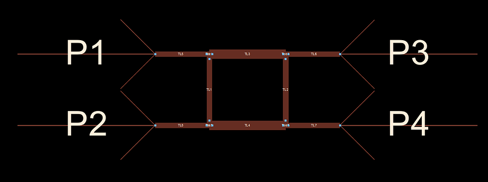
In this short tutorial/article I am going to show a few tricks and key settings to increase accuracy for both Momentum Microwave and FEM in ADS, and at the end you’ll see how the results from both of these EM simulation softwares get closer to each other and converge. The circuit that will be used to show this is going to be a simple 3 dB quadrature (90º) hybrid coupler, which is shown below.

I am particularly interested in S(1,1) and S(4,1). Let us simulate S(1,1) and S(4,1) of the coupler and compare the results from these different simulators. In the figure below we can see different results. By the way ADS 2016 is used.

In figure.2 we can clearly see that the results are not in great agreement. Especially S(1,1)’s are quite different from each other. I am now going to show you the key elements to increase accuracy for both simulators.
Accuracy Settings for Momentum Microwave
There are surely a lot of settings in Momentum microwave’s EM setup panel, but I am not going to clarify all of them. I am just going to show and explain the key compenents for accuracy. The main setting that basically increase the accuracy is mesh density. You can access mesh density settings in EM simulation setup > Options > Mesh > Mesh density. In mesh density menu by increasing Cells/wavelength you can increase accuracy, basically if you increase Cells/wavelength you get more accurate results. For quick and less accurate results you can set Cells/wavelength to 20 for accurate results, you can a number between 100-150 . In this menu you also have to turn “edge mesh” on. Lastly, set the mesh frequency at the frequency where the circuit has good amount of power, in this case it is 2 GHz. In figure.3 this menu is shown.

Accuracy Settings for FEM
In FEM simulator the dominating setting that affects the accuracy is Delto error. It can be accessed EM simulation setup > Options > Stop criterion. In this menu you can increase the accuracy of the simulation by decreasing Delta error. This setup basically determines mesh convergence. For fast and less accurate results you can use 0.1, but for accurate results you can use a number between 0.05 and 0.001, but keep in mind that if you set Delta error too low, the simulation can take ridicilous amount of time. Again in the same menu by increasing Maximum number of adaptive passes you can increase the accuracy. Last but not least in EM simulation setup > Options > Refinement you can click on manual selection and specify the frequency for mesh generation. As we discusses Momentum Microwave this frequency should be set to the frequncy where the circuit has good amount of power. Figures below show these settings.


Results
After setting Cells/wavelength and Delta error to 150 and 0.003 respectively and doing other settings that I discussed previously the results for the same circuit is shown below.

As it’s clearly seen in the figure.6 the results are in perfect agreement. You might not be able to see the difference in the graphs because they are completely overlapped.
Comments