Derivation of Richard’s Transform and its Application
- Alperen Akküncü

- Jun 3, 2018
- 2 min read
Richard’s transform is a useful method that is used in microwave/high-frequency filter design. LC ladder tables are usually used to design prototype filter and prototype filter is converted to stub/distributed element filter by using Richard’s transform. The reason for this conversion is that it’s very difficult to get accurate inductors and capacitor values that is required for the filter, but the length of the stubs can be made very accurate in PCB.
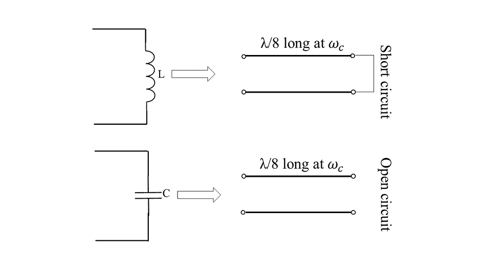
Before the derivation let us see what Richard’s transform actually does. What it basically does is that it converts inductors and capacitors to 1/8 wavelength long short stubs and open stubs respectively as shown in figure.1.
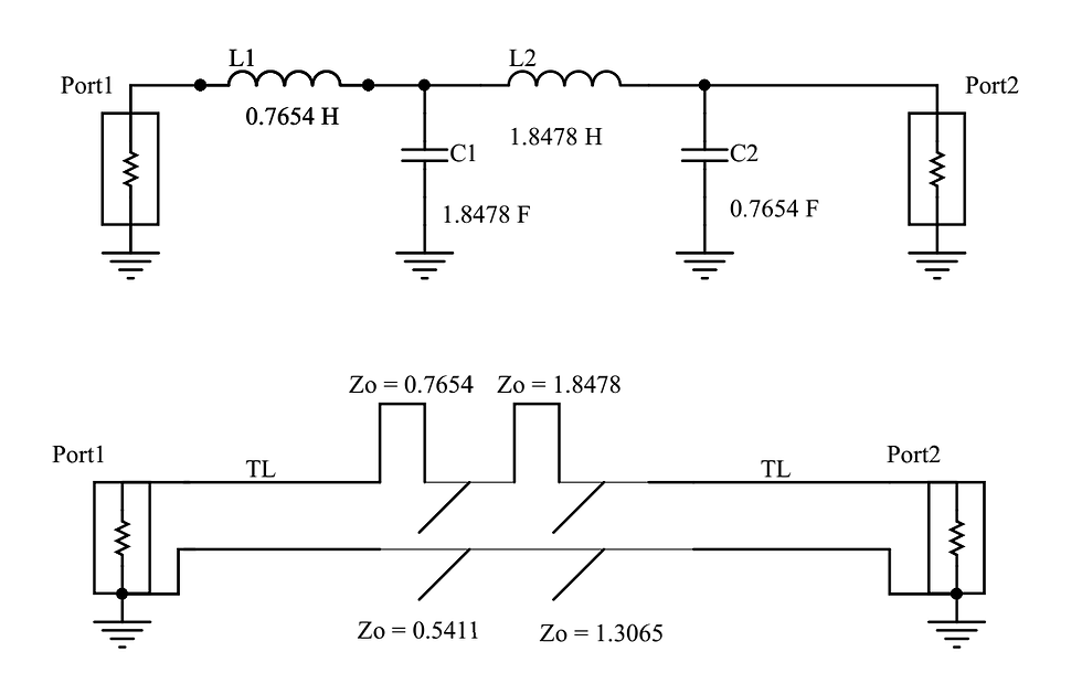
Richard’s transformation is very useful when designing filters. As it’s mentioned before it can convert LC ladder filters to stub filters as shown in figure.2. This stub filter in this form is not really practical and realizable because of the series short stubs, but it’s really useful as a starting point in filter design.
Let us first investigate the input impedance of 1/8 wavelength long short and open stubs. The input impedance of these type of stubs are shown below.
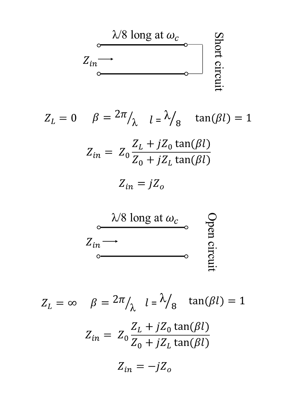
In figure.3 the equations for calculating the input impedance of 1/8 wavelength stubs are given. For short stubs the the load impedance (ZL) is simply 0 because the load is short circuit and for open stubs the load impedance (ZL) is infinity because of the open circuit at the end.
An important thing to realize here is that for short stub the impedance is purely imaginary and it’s positive and for short stub the impedance is also purely imaginary and it’s negative just like inductors and capacitors, respectively, and therefore we can use them as substitutes for capacitors and inductors.
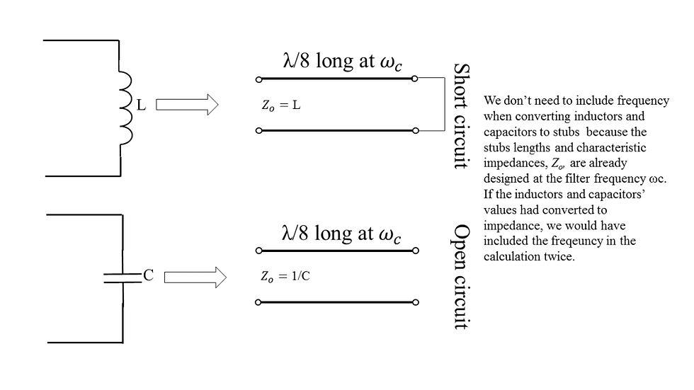
A crucial thing to realize here is that when converting from passive element (inductor/capacitor) to stub, we don’t need to calculate the impedance of passive elements because the impedance of passive elements are frequency dependent and this dependence is already taken care of when designing the stubs. Stubs are designed for specific characteristic impedance and length at the frequency of interest, and for that reason we don’t need to include frequency in our calculation twice by calculating the impedances of passive elements.
Finally, Figure.5 shows an example of conversion from prototype filter, i.e., a filter that is designed by using the LC ladder table, to stub filter. It’s a fourth order butterworth filter and the port impedances 1Ω.

Keep in mind that the filter is not practically realizable because of the series stubs (after all, how do you think they are going to look like in the PCB, hard to imagine right?). After using Richard’s transformation to convert prototype filter to stub filter it’s also necessary to use Kurodo’s identity to implement the filter physically.


Comments