Slew Rate Limiter Stability Analysis
- Alperen Akküncü

- Jun 1, 2018
- 3 min read
Updated: Jun 10, 2018
In this blog post we’re going to discuss the slew rate limiter and its stability analysis. Refrence [1]discusses its theory of operation and how to stabilize it, but it doesn’t show any information or calculation about stability and it also doesn’t tell how to stabilize the circuit when different resistor and capacitor values are used, and therefore I try to clarify this point in this post.
In [1] OPA192 is used as opamp, in this blog post , however, TL071 is used because I have a bunch of these in hand. It doesn’t matter what opamp you use because the procedure to stabilize any loop is very similar to what we are going to discuss here.

Figure.1 shows the actual circuit itself. We choose R=330kOhm and C = 1nF. In this case the slew rate will be 41000 V/s compared to 13V/us of opamp’s slewrate, 41000 V/s is quite small. (One of them is V/s the other is V/us, be careful about the units)
Open Loop Gain of TL071

The circuit in figure.2 is used to determine open-loop characteristics of TL071. TINA circuit simulation software from texas instruments is used to simulate the circuit. In this circuit a very large capacitor C1 is used to prevent DC coming from the VG1 source voltage and a very large inductor L1 is used to break the loop. This is simply a trick to break to loop, you can read more about it in [1] in section A.2. gain and phase response is plotted in figure.3a and figure.3b. You can find all simulation files that are used here.


In figure.3a and figure.3b it can be seen that this particular opamp has DC gain of 106dB and has poles at 15 Hz and 9.45 MHz. The open-loop transfer function of the opamp is,

Loop Gain of Slew Rate Limiter
Loop gain is calculated by breaking the feedback loop between U2’s output and U1’s noninverting input and figuring out the transfer function of the circuit shown in figure.4

The circuit in figure.4 is divided into 2 parts to simplify the analysis. U1(s) is basically the open loop gain of the TL071, which were found in the equation (4), but for the first stage only first will be included, as a result U1(s) will only have one pole. U2(s) is basically an integrator therefore U2(s) has 3 poles, one of them is because of the capacitor in the feedback and two of them is because of the poles of the opamp. The overall transfer function of the loop gain is going to be the multiplication of U1(s) and U2(s). Thus,

The loop gain has for poles therefore it is likely to oscillate. The following figure shows the bode plot of the loop gain. It was plotted in matlab and you can find the matlab code here.


Clearly, figure.5 shows that the slew rate limiter is not stable and figure.6 shows the transient waveforms of the input and output. To stabilize the loop we need to find a way to add a zero just before the 0 dB crossing (in this case the 0 dB crossing is at 38 kHz). In refrence [1] to stabilize the loop, a resistor is added in series with the capacitor. Let us see how this resistor affects the loop gain transfer function. After adding the resistor the circuit looks like this,

Realize that the loop gain is still U1(s)*U2(s) only U2(s) changes. Let us now see how the resistor in series with the capacitor affects the loop gain,

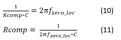
Equation (5) is substituted to equation (9). When the resistor Rcomp is added, In (8) we see that there is a zero added to 1/(Rcomp*C) rad/s. Therefore we can add a zero to the loop gain and by choosing the value of Rcomp we can select the zero’s location. Equations (10) and (11) are useful for determining the location of zero.

Remember we were trying too add a zero just before 38kHz, choosing Rcomp = 4.2kOhm adds a zero at 37.8 kHz, which is just before 38 kHz. Remember C = 1nF.
After adding the resistor the bode plot of the compensated loop gain is plotted below.

As we can see in figure.8 we have very safe phase and gain margins.
To assure that compensation was succesful the output waveform is observed before and after the compensation resistor is added. Waveforms of input and output are shown below.

URL to the Refrences and Materials
[1] TI Precision Designs: Reference Design Single Op-Amp Slew Rate Limiter URL: http://www.ti.com/lit/ug/tidu026/tidu026.pdf
[2] Tina Spice-based analog simulation program URL : http://www.ti.com/tool/tina-ti
[3] Matlab code used in this post : https://drive.google.com/open?id=0B3fWc2ZL6_xAVXdzTEx5V3VuZ0k
[4] Simulation files used in this post : https://drive.google.com/open?id=0B3fWc2ZL6_xALV9yS2JZaGRoeFU


Comments